Electric Motors
To propel an electric vehicle, electricity must be converted to mechanical force. Electric motors use current flowing through wires to create magnetic fields that interact with other magnetic fields in the motor to create motion.
Contents
DC Motors
DC motors are electro-mechanical machines which take DC inputs to generate torque. These machines include Brushed DC, Brushless DC machines (BLDC), and homopolar machines among others. While some use mechanical commutators like brushes, some DC machines commutate electrically based on the rotor position.
Brushed DC Motor
Brushed DC Motors are the conventional hobbyist motor and come in two main varieties: Permanent Magnet Based (PMDC) and Field-Winding Based (FWDC). They use mechanical brushes to commutate the the flow of current through the rotor to generate a torque. Because of this, they are easy to control, and do not require a position sensor to track the rotation of the motor. For the PMDC machine, the flux generated by the rotor interacts with the permanent magnet flux to generate torque. For the FWDC machine, the permanent magnets are replaced by another set of coils which generate the stator flux. This allows the machines to operate at high speeds using flux weakening techniques.
For FSAE applications, Brushed DC machines can reduce system complexity; however, at higher power levels, these machines have low efficiencies and must have regular maintenance of brushes. In addition, these machines have relatively low torque and power density which can increase system mass and cause packaging issues. For these reasons, they are not commonly used in FSAE powertrains.
Brushless DC Motor
Brushless DC motors (BLDC) are another form of DC machines that commutate electrically (i.e. without brushes). BLDC machines typically consist of a rotor with permanent magnets and a stator which is wound such that the EMF has a trapezoidal shape. While the structure shares many similarities with the AC Synchronous machines, the distinction is in the control methodology and corresponding winding structure.
Rather than using a high resolution control algorithm like Field Oriented Control, BLDC motors use a heavily discretized, six-step control method. This is implemented by commanding a DC voltage (averaged through PWM) through two of the motor phases based on the rotor position. This is implemented by Hall Effect sensors embedded in the machine which determine which of the six possible phases to regulate current in.
In addition to the Hall Effect sensor used for commutation, BLDC motors often use an encoder to track the rotational position and velocity of the motor for control purposes.
BLDC motors are advantageous for their high torque density (higher than SMPM machines); however, the six-step method generates a large amount of torque ripple which reduces efficiency. BLDC machines also cannot flux weaken with conventional techniques, so problems can arise at higher speeds if voltage limited.
AC Synchronous Motors
AC Synchronous Machines a class of machines characterized by the fact that their rotor flux is synchronous with the rotor angle. These category includes surface mount (SMPM), synchronous reluctance (synRel), and interior permanent magnet (IPM) machines among others. These machines use PM or mutual torque along with reluctance torque to generate torque over a wide speed range. AC Synchronous machines also have sinusoidal EMFs due to their winding distribution. These machines typically use high performance control aglorithms like Field Oriented Control which require a high resolution position sensors like a resolver.
Surface Mount Permanent Magnet Machines
Surface mount permanent magnet machines (SMPM) are the most straight-forward type of synchronous machines. The stator usually has a sinusoidal winding distribution and the rotor contains permanent magnets on the surface of the rotor iron.
Because the permeability of the magnets is close to air, the ideal SMPM has no rotor saliency and therefore no reluctance torque. The resultant torque expression is dependent solely on the current orthogonal to the rotor flux.

Where...
Failed to parse (MathML with SVG or PNG fallback (recommended for modern browsers and accessibility tools): Invalid response ("Math extension cannot connect to Restbase.") from server "https://wikimedia.org/api/rest_v1/":): {\displaystyle Np} = Number of Motor Poles
Failed to parse (MathML with SVG or PNG fallback (recommended for modern browsers and accessibility tools): Invalid response ("Math extension cannot connect to Restbase.") from server "https://wikimedia.org/api/rest_v1/":): {\displaystyle \Lambda_{PM}} = Permanent Magnet Flux Linkage
Failed to parse (MathML with SVG or PNG fallback (recommended for modern browsers and accessibility tools): Invalid response ("Math extension cannot connect to Restbase.") from server "https://wikimedia.org/api/rest_v1/":): {\displaystyle I_q^r} = Quadrature Current in rotor reference frame
For FSAE, SMPMs are good choice because of their high torque density and efficiency. At low speeds SMPM machines can also achieve unity power factor which is ideal when the vehicle is power limited. Using Field oriented control, SMPM's can flux-weaken as well to achieve higher speeds. Depending on the inductance of the machine, can achieve constant power after a certain speed.
Synchronous Reluctance Machines
Rather than using permanent magnets, Synchronous Reluctance (SynRel) Machines rely on the magnetic saliency of the rotor to generate a reluctance torque. These machines are not as common as there SMPM counterparts, but they allow easy control of the flux in the machine.
Failed to parse (MathML with SVG or PNG fallback (recommended for modern browsers and accessibility tools): Invalid response ("Math extension cannot connect to Restbase.") from server "https://wikimedia.org/api/rest_v1/":): {\displaystyle \tau = \frac{3Np}{4}(L_d - L_q)I_d^rI_q^r }
Where...
Failed to parse (MathML with SVG or PNG fallback (recommended for modern browsers and accessibility tools): Invalid response ("Math extension cannot connect to Restbase.") from server "https://wikimedia.org/api/rest_v1/":): {\displaystyle Np} = Number of Motor Poles
Failed to parse (MathML with SVG or PNG fallback (recommended for modern browsers and accessibility tools): Invalid response ("Math extension cannot connect to Restbase.") from server "https://wikimedia.org/api/rest_v1/":): {\displaystyle L_q} = Quadrature Axis Inductance in rotor reference frame
Failed to parse (MathML with SVG or PNG fallback (recommended for modern browsers and accessibility tools): Invalid response ("Math extension cannot connect to Restbase.") from server "https://wikimedia.org/api/rest_v1/":): {\displaystyle L_d} = Direct Axis Inductance in rotor reference frame
Failed to parse (MathML with SVG or PNG fallback (recommended for modern browsers and accessibility tools): Invalid response ("Math extension cannot connect to Restbase.") from server "https://wikimedia.org/api/rest_v1/":): {\displaystyle I_q^r} = Quadrature Axis Current in rotor reference frame
Failed to parse (MathML with SVG or PNG fallback (recommended for modern browsers and accessibility tools): Invalid response ("Math extension cannot connect to Restbase.") from server "https://wikimedia.org/api/rest_v1/":): {\displaystyle I_d^r} = Direct Axis Current in rotor reference frame
Because they do not contain permanent magnets, they are often thought of as the synchronous analogy to induction machines. Furthermore, a variation of SynRel machines, Switched Reluctance Machines, are often thought of as BLDC Machines are to SMPM machines.
Interior Permanent Magnet Machines
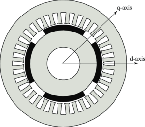
Interior Permanent Magnet (IPM) Machines are newer type of synchronous machine that embed the rotor magnets in the rotor iron. There are several different types of IPM machines including inset, embedded, spoke, etc. Because the magnets which have a low incremental permeability are embedded in the highly permeable rotor iron, IPM machines a substantial rotor saliency. IPM machines, therefore, can use both permanent magnet and reluctance torque.
Failed to parse (MathML with SVG or PNG fallback (recommended for modern browsers and accessibility tools): Invalid response ("Math extension cannot connect to Restbase.") from server "https://wikimedia.org/api/rest_v1/":): {\displaystyle \tau = \frac{3Np}{4}((L_d - L_q)I_d^r+\Lambda_{PM})I_q^r }
Where...
Failed to parse (MathML with SVG or PNG fallback (recommended for modern browsers and accessibility tools): Invalid response ("Math extension cannot connect to Restbase.") from server "https://wikimedia.org/api/rest_v1/":): {\displaystyle Np} = Number of Motor Poles
Failed to parse (MathML with SVG or PNG fallback (recommended for modern browsers and accessibility tools): Invalid response ("Math extension cannot connect to Restbase.") from server "https://wikimedia.org/api/rest_v1/":): {\displaystyle \Lambda_{PM}} = Permanent Magnet Flux Linkage
Failed to parse (MathML with SVG or PNG fallback (recommended for modern browsers and accessibility tools): Invalid response ("Math extension cannot connect to Restbase.") from server "https://wikimedia.org/api/rest_v1/":): {\displaystyle L_q} = Quadrature Axis Inductance in rotor reference frame
Failed to parse (MathML with SVG or PNG fallback (recommended for modern browsers and accessibility tools): Invalid response ("Math extension cannot connect to Restbase.") from server "https://wikimedia.org/api/rest_v1/":): {\displaystyle L_d} = Direct Axis Inductance in rotor reference frame
Failed to parse (MathML with SVG or PNG fallback (recommended for modern browsers and accessibility tools): Invalid response ("Math extension cannot connect to Restbase.") from server "https://wikimedia.org/api/rest_v1/":): {\displaystyle I_q^r} = Quadrature Axis Current in rotor reference frame
Failed to parse (MathML with SVG or PNG fallback (recommended for modern browsers and accessibility tools): Invalid response ("Math extension cannot connect to Restbase.") from server "https://wikimedia.org/api/rest_v1/":): {\displaystyle I_d^r} = Direct Axis Current in rotor reference frame
IPM machines are advantageous for multiple reasons. First, because the magnets are embedded in the rotor, the magnets see predominately compressive forces rather than tensile in SMPM designs at high speeds. Because high performance magnets can withstand higher compressive forces than tensile, IPM motors can typically run at higher speeds than SMPM machines. Second, because of IPM's saliency and large inductance's, these machines can easily flux weaken and achieve constant power over a wide speeds range.

