Difference between revisions of "Intake"
SpookySimon (talk | contribs) |
SpookySimon (talk | contribs) |
||
| Line 88: | Line 88: | ||
{{#evt:service=youtube|id=https://www.youtube.com/watch?v=-l7o64Tc5hk|alignment=right}} | {{#evt:service=youtube|id=https://www.youtube.com/watch?v=-l7o64Tc5hk|alignment=right}} | ||
<!--Video could use a revision, the low level explanation is good, but I think it might plant some seeds that are either incorrect or misleading, like the air in the intake shouldn't "bounce" backwards, the energy does in a sound wave, but the air itself doesn't go up and down the intake. The air also does not bounce off the throttle, it is usually reflected at a dramatic cross sectional area change like the plenum--> | <!--Video could use a revision, the low level explanation is good, but I think it might plant some seeds that are either incorrect or misleading, like the air in the intake shouldn't "bounce" backwards, the energy does in a sound wave, but the air itself doesn't go up and down the intake. The air also does not bounce off the throttle, it is usually reflected at a dramatic cross sectional area change like the plenum--> | ||
| + | |||
| + | A typical intake valve will open before TDC and close after BDC. When the piston travels down to begin the intake stroke, the pressure in the cylinder drops. This pressure differential draws air through the intake port from the runner, and plenum. The pressure at each of these points continues to drop as the piston continues to travel down. This develops a low pressure (rarefaction) wave which will travel back up the intake runner. Once the low pressure wave hits the change in volume of the plenum, it is reflected back down the intake runner as a positive pressure wave. | ||
| + | |||
| + | It is a common misconception among FSAE students and adults who work on engines that the pressure wave mechanism is due to the air "bouncing" off of the closed intake valve, this is incorrect. If that was true, the positive pressure wave generated by this will reflect back at the plenum interface as a negative pressure wave and cause a deleterious effect when "tuned". | ||
| + | |||
| + | The piston begins to travel up before the intake valve closes. This does increase pressure in the cylinder and runner which can cause reverse flow at very low engine speeds but is generally neglected. At medium to high engine speeds, the momentum of the air flow into the cylinder will continue to drive air into the cylinder even after BDC. This effect of momentum is known as the "ram effect". | ||
Resonance tuning is implemented by modifying the length of the manifold such that the pressure wave formed on each cycle travels along the manifold and is reflected back, arriving just as the cylinder completes the cycle and takes in its next charge. When done correctly, the pressure at at the intake port will be higher during the intake stroke, giving better volumetric efficiency for the engine. The parameters to adjust are the length of your intake runners and their diameter. Intake runner length is often the easiest parameter to tune and often has the biggest impact on the system. A longer runner will resonate at a lower frequency. A larger diameter intake runner will lower the speed of the air, raising the resonant frequency for a fixed length (someone check me on this). | Resonance tuning is implemented by modifying the length of the manifold such that the pressure wave formed on each cycle travels along the manifold and is reflected back, arriving just as the cylinder completes the cycle and takes in its next charge. When done correctly, the pressure at at the intake port will be higher during the intake stroke, giving better volumetric efficiency for the engine. The parameters to adjust are the length of your intake runners and their diameter. Intake runner length is often the easiest parameter to tune and often has the biggest impact on the system. A longer runner will resonate at a lower frequency. A larger diameter intake runner will lower the speed of the air, raising the resonant frequency for a fixed length (someone check me on this). | ||
| − | In more complex | + | In more complex tuning applications, actuated baffles can be created to vary engine torque curve. This is done on many production cars to allow different behavior at low and high RPM. |
===Trade-Offs=== | ===Trade-Offs=== | ||
The fundamental tradeoff with most intake tuning is to prioritize a higher peak torque or a wider, flatter torque curve. | The fundamental tradeoff with most intake tuning is to prioritize a higher peak torque or a wider, flatter torque curve. | ||
Latest revision as of 14:39, 19 May 2025
The intake system has a dominant effect on the torque curve and behavior of the powertrain system. All air used by the engine(s) for combustion must pass through a 20 mm or 19 mm opening for gasoline or E85 fueled vehicles respectively, commonly referred to as a restrictor. The restrictor limits the theoretical power limit of the engine.
Contents
Intake Design
Structure

Following the path the air follows as it enters the engine, the naturally aspirated intake system is made of the following components: the air filter, the throttle body, the restrictor, the plenum, the manifold, and the engine mounting. The air filter's sole responsibility is to stop water or particulates from entering the engine, these could cause engine damage or even failure. The throttle body allows for driver modulation of mass air flow into the engine, there-by controlling engine torque and speed. The plenum acts as a capacitor to smooth air flow into the cylinders and can be tuned to increase volumetric efficiency. The manifold consists of runners that channel air from the plenum into each cylinder.

In forced induction applications, allowing a manifold between the restrictor and throttle body will limit the effects of the restriction. This is negated in FSAE by preventing a large volume (plenum/manifold, intercooler, etc.) prior to the throttle body (Rule IC.2.5.3). The order of system components defined by rules can be seen in the figure right and each component is discussed further down this page.
Packaging

Packaging of the intake manifold has minor if any impact on the performance of the engine, but it can impact the aerodynamics of the car, particularly the rear wing (if the car has one). All intake packaging schemes can be categorized into the following: A top feed (or center feed), Side feed, and bottom feed. Although not true for every team, the choice is often based on manufacturing, serviceability and similar non-performance goals. Certain form factors lend themselves to intake manifold styles and vice-versa. Conical spline intakes are almost always found in a center feed configuration. Log style intake manifolds when used in a side feed configuration can be packaged very tight.
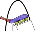
Side Feed
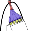
Top-Center Feed
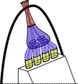
Conical Spline


Material Choice
The material used for the intake has a much lower impact on the performance than other tuning variables but warrants consideration. The major driving factors to consider are feasibility related: whether it is cost-effective, feasible to create the design the team has made, reliable enough to last through testing and competition, and similar. There are of course differences in the materials chosen that will be discussed here, but is important to understand the material choice is not expected to make a significant difference in dynamic event performance.
Common materials used by teams are below
Please add to this list if your team uses a material not mentioned here
| Type | Material | Construstion | Notes |
|---|---|---|---|
| Metals | Aluminum | Welded sheet and tubing | May exchange heat with ambient air if not coated |
| Plastic | Nylon | Usually 3D printed | Nylon is one of the few 3D printable plastics that is gasoline resistant |
| Nylon - Carbon or Glass Fiber Reinforced | Usually 3D printed | Often outsourced, many institutions do not have in house capabilities to print this or won't want to | |
| Ultem/PEI | 3D Printed | ||
| Other | Off the shelf injection molded | Available 3rd party solutions | |
| Composite | Carbon Fiber | Vacuum bagged, Infusion, Prepreg | |
| Fiberglass | Vacuum bagged, Infusion | Not as common as carbon fiber |
Plenum
Because the engine takes in air in only one part of the combustion cycle, the airflow out of the intake system is inherently pulsed. The pulsing allows less mass airflow into the system than a smooth airflow would (for many reasons, the most basic of which being that the low pressure waves reduce the airflow more than the high pressure waves increase it).
One useful analogy is comparing the system to a circuit where the output current is pulsed. The restrictor acts as a resistor (hopefully obvious). A basic way to smooth out the circuit is to add a capacitor. In the real world, we do this by adding a volume of air after the restrictor known as a plenum.
The plenum in series with the restrictor creates a pseudo low pass filter that will help smooth out the pulsed air flow characteristics of the intake. Since the restrictor is a fixed size, the "circuit" is tuned by changing the capacity (capacitance hint hint) of the plenum. If the plenum is too small, the non-uniform nature of the intake will significantly decrease power output. If the plenum is too large, the throttle will no longer be able to predictably control the air flow.
The size of the plenum is tuned imperically with many FSAE papers available for comparison. The shape of the plenum can be assumed to be negligible, the dominant characteristics of the plenum shape will likely be your discharge/flow coefficients at the interface to the restrictor and runners.
The phrase dual plenum can refer to two different designs, two plenum volumes in parallel (often called dual plane) or two in series. Lawrence Technical ran a two in parallel plenum design, tying a pair of cylinders to each plenum[1]. Series plenums are used to equalize airflow to the cylinders on intakes where the runners are not equidistant to the throttle body. These are most common on side intake log-style manifolds[2].
Intake Tuning
Tuning the intake is either modifying the system's response to different engine speeds, reducing pressure losses the air has to overcome, or adjusting the turbulence of the flow to aid in charge mixing. The most common and impactful form of tuning is changing the response to different engine speeds, or the engine's frequency response. This takes two forms: the first is in modifying the length of the manifold and the second is in modifying the shape of the manifold.(including Helmholtz resonators).
The basic principle behind frequency focused tuning strategies is that a cylinder draws air differently during different parts of the four stroke cycle. Ostensibly, a cylinder only takes in air for a quarter of a four stroke cycle, meaning that there is a stop-starting of the flow of air into the cylinder. This occurs at a frequency dependent on the rpm of the engine, hence this form of tuning is done to optimize performance at a selected rpm range.
The torque curve can be viewed as a frequency response curve.
Resonance Tuning
A typical intake valve will open before TDC and close after BDC. When the piston travels down to begin the intake stroke, the pressure in the cylinder drops. This pressure differential draws air through the intake port from the runner, and plenum. The pressure at each of these points continues to drop as the piston continues to travel down. This develops a low pressure (rarefaction) wave which will travel back up the intake runner. Once the low pressure wave hits the change in volume of the plenum, it is reflected back down the intake runner as a positive pressure wave.
It is a common misconception among FSAE students and adults who work on engines that the pressure wave mechanism is due to the air "bouncing" off of the closed intake valve, this is incorrect. If that was true, the positive pressure wave generated by this will reflect back at the plenum interface as a negative pressure wave and cause a deleterious effect when "tuned".
The piston begins to travel up before the intake valve closes. This does increase pressure in the cylinder and runner which can cause reverse flow at very low engine speeds but is generally neglected. At medium to high engine speeds, the momentum of the air flow into the cylinder will continue to drive air into the cylinder even after BDC. This effect of momentum is known as the "ram effect".
Resonance tuning is implemented by modifying the length of the manifold such that the pressure wave formed on each cycle travels along the manifold and is reflected back, arriving just as the cylinder completes the cycle and takes in its next charge. When done correctly, the pressure at at the intake port will be higher during the intake stroke, giving better volumetric efficiency for the engine. The parameters to adjust are the length of your intake runners and their diameter. Intake runner length is often the easiest parameter to tune and often has the biggest impact on the system. A longer runner will resonate at a lower frequency. A larger diameter intake runner will lower the speed of the air, raising the resonant frequency for a fixed length (someone check me on this).
In more complex tuning applications, actuated baffles can be created to vary engine torque curve. This is done on many production cars to allow different behavior at low and high RPM.
Trade-Offs
The fundamental tradeoff with most intake tuning is to prioritize a higher peak torque or a wider, flatter torque curve.
Pros
- All intake systems have this frequency response, so you do not need extra features to enable tuning
- Relatively simple system
- Allows for movement of your torque curve
Cons
- Simulations are often inaccurate and may require on vehicle testing to confirm optimal performance
- Can only tune to one optimal frequency, unless baffles are integrated
Helmholtz Resonators
Helmholtz resonators work by having a thin neck followed by an open cavity attached to the engine's intake. Their design result in low pressure at the neck, sucking in more air, and resulting in higher pressure air in the cavity, which can then feed the engine. They can be thought of as tuned mass dampers (and can be modeled as such). Helmholtz resonators are most effective in single cylinder systems, as the flow through the intake can be dominated by pulsed flow characteristics at high rpms [citation definitely needed]. These are most often seen in exhaust systems to control the sound output.
Trade-Offs
Pros
Helmholtz tuning can be used to suppress an unwanted torque spike somewhere in the curve.
Cons
Helmholtz tuning is very hard to predict, and requires a complex additional feature that may be difficult to package and have an unpredictable or negligible effect on performance.
Throttle Control
- Main page: Throttle
The throttle allows modulation of the air coming into your intake system. Within FSAE, the throttle must fall between your restrictor and manifold or, in boosted applications, between the turbocharger/supercharger and manifold. Throttle designs include actuation by throttle cable or by electronic throttle body (ETC or drive-by-wire).
Restrictor
- Main page: Restrictor
According to IC.2.4.1, the competition requires all air entering the engine to first pass through a 20mm diameter hole when using gasoline or a 19mm hole when using e85. This restrictor places a theoretical upper limit on the power that can be generated by a naturally aspirated engine. This is checked in competition by removing the throttle body and inserting a test instrument of the appropriate size in a go-no-go test.
Forced Induction
Forced induction is done by utilizing a compressor to increase the pressure seen in your manifold/plenum, leading to increased engine power and efficiency. This is accomplished by the higher manifold pressures being able to force more air into the cylinder/s on each intake stroke. The increased air in the cylinder means you can burn more fuel and maintain the same air-fuel-ratio. A denser charge will also combust faster, yielding greater energy utilization and efficiency. Common methods of implementing forced induction is by turbocharging, supercharging, or procharging. Within FSAE, a fair number of teams run forced induction, but the majority remain naturally aspirated. [3]
Turbocharging
Theory

A turbocharger works by compressing intake air by harvesting waste enthalpy, traditionally discarded, from the exhaust. The general flow of air through a turbocharged system can be seen to the right. Theoretically, the higher plenum pressure you can run, the more power you can extract from your engine package. One limiting factor is self-detonation of the charge or knock. The liability to knock is based upon many factors, including but not limited to, fuel choice, fuel injection location, and compression ratio.
Cooling Charge Air
The charge air cooler, also known as an intercooler, is designed to lower your charge air temperature. The intake air temperature increases due to compression, according to the equation for compressor pressure ratio.
- (P2/P1) = (T2/T1)γ/(γ-1)
Gamma is 1.4 for dry air. This equation must be used with absolute pressure and temperature. P2/P1 is also known as pressure ratio. For example, a pressure ratio of two (1 atm to 2 atm) will lead to a 20% increase in intake air temperature. This means for an inlet temperature of 20C, your plenum temperature will be approximately 85C. If you run low boost, the need for an intercooler may be able to be avoided. Alternatively, injecting E85 upstream of the runner to cool the air via the evaporation may be feasible. This is only done due to the high latent heat of evaporation and low evaporation temperature for E85. This method is beneficial as it provides cooling and well mixed air fuel mixture. However, this method requires an extremely careful tune otherwise your plenum is liable to turn into shrapnel.
Blow Off Valve
The purpose of a blow off valve (BOV) is to control your plenum/manifold pressure and prevent compressor surge by dumping excess flow. This works in conjunction with a wastegate to manage plenum pressure to your desired pressure.
Trade-Offs
Supercharging/Procharging
ETS pls
Theory
Trade-Offs
Forced Induction Manifold Designs
For Turbos:
Connecting the intake and exhaust manifolds
- Over the top
- Around the side
- I dont think anyones gone under the engine but im not willing to put money on it
avoid heating intake with exhaust headers
intercooler placement, mounting, (maybe do this in the cooling section?)
References
- ↑ Jawad, Badih A., et al. “Formula SAE Dual Plenum Induction System Design.” SAE Technical Paper Series, 2002, https://doi.org/10.4271/2002-01-0457. I have it on relatively good authority that the team that ran this setup also cheated the intake restrictor diameter by using a non-circular opening. Additionally my coworker who was on the team claimed they also ran a PCV line from the crank to the intake after the restrictor and vented the crank case to ambient so they were able to pull additional air through the crank case, unsure of the veracity of this claim.
- ↑ Bufkin, James. “Study of Intake Manifolds Used by Audi Sport for the Inline 5.” Bufkin Engineering, Inc., 29 Nov. 2004, https://www.bufkinengineering.com/intake%20manifolds.htm.
- ↑ At the 2018 FSAE Michigan competition 9 teams out of 120 (?) openly used forced induction: UMich (CBR), Cornell (CBR), Wisconsin (YZ450), Kettering (WR450), Rose (YZ450), UNC Charlotte (510cc single, KTM?), Minnesota Mankato (YZ450), UNH (KTM 450), Quebec-Chicoutimi (Genesis 80fi), Mississippi (CBR)
