Difference between revisions of "Drivetrain"
SpookySimon (talk | contribs) (→Final Drive Ratio: more words on choosing fdr, fixing error with large ratio/small ratio) |
SpookySimon (talk | contribs) (→Differentials: Intro Paragraph, see main page for details) |
||
| Line 72: | Line 72: | ||
=Differentials= | =Differentials= | ||
{{main|Differential}} | {{main|Differential}} | ||
| + | A differential allows the drivetrain to split torque to two wheels (or two other driveshafts for AWD) while allowing each wheel to rotate at different speeds. This facilitates turning at higher speeds and can help reduce, control, or even magnify understeer caused by the rear wheels being driven. The two main varieties are open and limited slip. High performance cars and most FSAE teams opt for limited slip type differentials because of their locking functionality and tunability, but many successful FS/FSAE teams have competed using an open differential or a spool (functionally equivalent to a welded differential). | ||
| + | |||
=Driveshafts= | =Driveshafts= | ||
Driveshafts, or half-shafts, are needed to transfer the torque from the [[differential]] or [[Differential#Spool|spool]] to the wheel. Because the wheels move with respect to the rest of the car, the driveshafts will have to be able to articulate while turning. This is achieved by implementing a constant velocity (CV) joint. | Driveshafts, or half-shafts, are needed to transfer the torque from the [[differential]] or [[Differential#Spool|spool]] to the wheel. Because the wheels move with respect to the rest of the car, the driveshafts will have to be able to articulate while turning. This is achieved by implementing a constant velocity (CV) joint. | ||
Revision as of 11:34, 19 January 2023
A system is needed to transfer mechanical energy from the engine or electric motor to the ground. The train takes the rotational mechanical energy from the engine and transfers it to the wheels.
Contents
Gearing
- Main page: Gearing
The first stop in the torque train coming out of engine/motor station is the transmission. The engine's gearing determines crawl speed (lowest speed of the vehicle without the brake or clutch applied), top speed and torque availability at any vehicle speed in between. For most motorcycle engines, this is a set of internal gears that can be selected by the driver. For electric vehicles, the transmission is often a single speed reduction gear.
The design engineer will need to also be mindful of how much tractive force the vehicle will generate in any given gear. This plays with tire selection and helps determine what happens when the driver firewalls the go pedal.
This also plays into forces on the differential and driveline components.
Motorcycle Gearboxes
Motorcycle engines have internal sequential gearboxes. This is means that the gearing is located inside the crankcase. The lubrication is managed by the engine's oil system. Typically, these are 5 (YZ450) or 6 speeds (CBR600RR). Drivetrain efficiency for a geared system is often as high as 98% [1].
Clutch
Most motorcycles use a wet plate clutch pack whereas most cars use a single dry plate clutch. Wet plate clutch packs are immersed in oil (wet) and use multiple friction plates (known as a pack).
The motorcycle clutch uses a set of linear springs or a diaphram (less common). When engaged, the springs squeeze a series of clutch plates tight enough to restrict relative rotation. This mechanically links the engine output to the crankshaft. When disengaged, the plates are under no pressure and have the ability to rotate freely relative to one another. This allows the engine to spin without outputting a torque.
Continuously Variable Transmissions
These allow for an infinite combination of engine to wheel speeds. The benefits of this include allowing the engine to be run at peak power, peak efficiency, or peak torque at any vehicle speeds. The downsides are lower efficiency (~88% effficient) [2] and a lower peak torque transfer.
Gear Selection
- Main page: Shifter
If your car has more than one gear, it's likely dependent on the driver to select which one the car should be in at any given time. This can be done by adapting a shifting mechanism to the motorcycle's shift lever (or shift drum or what have you)
Drive Mechanisms
There are two ways to get power from the engine to the tires: connecting the engine output shaft directly to the wheel(s) being driven (direct drive) or transmit the power from the engine to the wheels through an intermediate mechanism (indirect drive). For combustion vehicles, indirect drives are the prevalent design as it allows for a flexibility of engine placement relative to wheels, a greater degree of drive ratios, and it often easier to implement. [citation or explanation needed]
Indirect Drive
Chain Drive
- Main page: Chain Drive
Power transmission using a chain drive uses a drive sprocket on the engine connected by a chain to a driven sprocket on the rear axle(s). A chain drive is the most common system found in FS for a few reasons: most motorcycles already use this system, and it is easy to convert the existing system to drive a formula car, the system is robust, and the minimum design work to implement a functional system is limited. Factors that can limit design work include:
- The system has a low part count
- Many OEM or equivalent sprockets are available
- The system requires no pretension
- A chain has no slip
- There is a wide margin of error for design flaws except planar misalignment
Belt Drive
Power can also be transmitted with a belt and two pulleys. A belt and pulley does not require lubrication, but still needs a tensioner (also needs to be pretensioned or else you'll get big slip). Pulleys are more expensive than sprockets [citation needed] and can be difficult to manufacture for most teams [citation or explanation needed, is it hard to design but easy to manufacture or both or easy to design but hard to manufacture?]. The chordal action is less apparent on belt drives because the pulley is more circular than a sprocket.
-system allows slip
CVT
CVTs are commonly used on snowmobile engines such as ___. can be done w belt or laminated chain(which could be argued to just be a belt)
Driveshaft
Not common on motorcycles, driveshafts are generally used for front engine, rear wheel drive cars. Some motorcycles do have them, mostly BMWs. They are more expensive and cannot as easily be customized to a new length.
Gear Drive
High-Octane Motorsports (out of Erlangen-Nurnberg) ran longitudinally mounted engine and bevel gear drive[3]
Direct Drive
Drivetrain Shield
Drivetrain shields are covered under the FSAE rule T.5.2. Chain drive shields are subject to stricter rules, requiring a wider shield made of steel. A belt drive system is allowed an aluminum shield of a narrower width. Frame tubes are allowed to act as part of the shield given they pass the material requirements. OEM chain guards on the engine itself such as on the CBR600RR are accepted as part of the chain guard as well. If any part of a brake line or cable carrying traction voltage passes across the chain, it also needs to be shielded by the chain guard or equivalent; this is an especially common issue in tech if the line crosses underneath the chain. This infraction is checked at tech by line of sight.
A drivetrain shield is easy to check before tech inspection and usually too time consuming to complete during.
Final Drive Ratio
The final drive ratio (FDR) is the gearing reduction between the transmission output shaft and the differential. Because most motorcycle gearboxes come stock with the engine, and are usually similar in design, the final drive ratio is the easiest impact the team can have on the vehicle's gearing. Changing the FDR to a larger ratio will result in a lower top speed, close gearing, and higher acceleration. A smaller ratio will result in a higher top speed, wide gearing, and lower acceleration.
One often overlooked issue with especially tall FDRs is packaging the large rear sprocket. Usually the FDR is chosen to meet acceleration goals as the engines can rev high enough to achieve the top speed of the autocross style courses being driven. A shorter FDR can also reduce the number of gear shifts the driver will make over the course if driver competency is a driving factor in vehicle design.
Traction Model

A traction model or tractive force diagram is used to analyze the vehicle's drivetrain. Tractive force is plotted against vehicle speed to visualize how much torque, thrust or traction the vehicle will be able to generate at a speed. Curves denoting the limit of traction and drag is plotted on the same graph. Aerodynamic forces cause the limit of traction and drag forces to increase exponentially with vehicle speed. Then, the torque curve of the engine is multiplied by the gear ratios for each gear in the transmission and the final drive ratio. To get force from the torque, this number is then divided by the tire's dynamic radius (FxR = T).
A car that runs a high power engine like a CBR with a tall final drive ratio may find that the peak torque from the first gear is partially or entirely beyond the limit of traction. This would prevent the driver form being able to utilize the full torque the engine can produce until high in the first gear or even until shifting to second gear. The team could shorten the FDR to move more of the peak torque of the first gear beneath the limit of traction as shown in the second image. Additionally, the team could remove the first gear of the CBR, stretching the graph to the left as seen in the third image. Remember: this is not necessarily the route your team will want to go. A skilled driver can better handle the limits of the car without being spoonfed or strapped to an underpowered machine. YMMV.
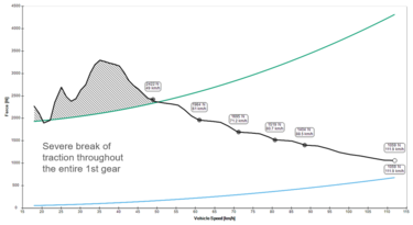
Example of a Tractive Force Diagram
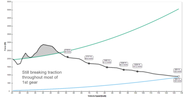
The Same Tractive Force Diagram with a Reduced FDR
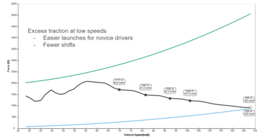
The Same Tractive Force Diagram with a Reduced FDR and Removal of the First Gear


This is why removal of the first gear is a common engine modification for the CBR
Differentials
- Main page: Differential
A differential allows the drivetrain to split torque to two wheels (or two other driveshafts for AWD) while allowing each wheel to rotate at different speeds. This facilitates turning at higher speeds and can help reduce, control, or even magnify understeer caused by the rear wheels being driven. The two main varieties are open and limited slip. High performance cars and most FSAE teams opt for limited slip type differentials because of their locking functionality and tunability, but many successful FS/FSAE teams have competed using an open differential or a spool (functionally equivalent to a welded differential).
Driveshafts
Driveshafts, or half-shafts, are needed to transfer the torque from the differential or spool to the wheel. Because the wheels move with respect to the rest of the car, the driveshafts will have to be able to articulate while turning. This is achieved by implementing a constant velocity (CV) joint.
Driveshaft Specifications
- Material
- how to safely change the length and heat-treat the HAZ
- lateral play
- splines
- should be outside the major shaft diameter
- circlip grooves/failures
- Torque Steer baby - probably make another page for this for details on concept and derivation

CV Joints
- tripods
- Most common, even referenced as fundamental part of the drivetrain design on the 2022 FSAE design scoresheet.
- Commercially available from RCV and Taylor
- those rubber shits
- flex plates
- See BYU 2008 [4]
Hubs
- Main page: Hubs
The driveshaft sends power to the wheel hub. The hub is held within the upright/knuckle with wheel bearings. Hubs can be lug/stud-centric, hub-centric, or center-lock.
Wheels
- Main page: Wheels
Validation
In vehicle simulations, including driveline affects become important the more detailed the vehicle model gets. The brake torque and horsepower are not what is seen by the tire's contact patch. A physical measurement of driveline forces should be undertaken at some point. It is not likely needed to do this every year however it should be done at least once to correlate model to reality.
This is typically a rotating measurement and typically involves the use of strain gauges. Wireless amplifiers are often needed. Several companies make them available such as Texense, Izze Racing and Lord Microstrain.
--Can talk more about the measurement in the electronics section. Maybe keep this higher level? You could right a whole section just on measurement techniques, uncertainty analysis, error influence coefficients.I think it is worth calling out a couple companies so teams at least have some direction. In the case of wireless strain gauge amps you can go down a real rabbit hole and not find what you need. As far as the gauge install itself, I think that is a lot easier to self research.
References
- ↑ Lopot, František, et al. “Gearbox Mechanical Efficiency Determination by Strain Gauges Direct Application.” Applied Sciences, vol. 11, no. 23, 24 Nov. 2021, https://doi.org/10.3390/app112311150.
- ↑ Heath, RPG. “Seamless AMT Offers Efficient Alternative to CVT.” JSAE Annual Congress, 2007.
- ↑ https://www.facebook.com/octanes/photos/3205416676163393
- ↑ https://jengineer.org/formula-sae/
